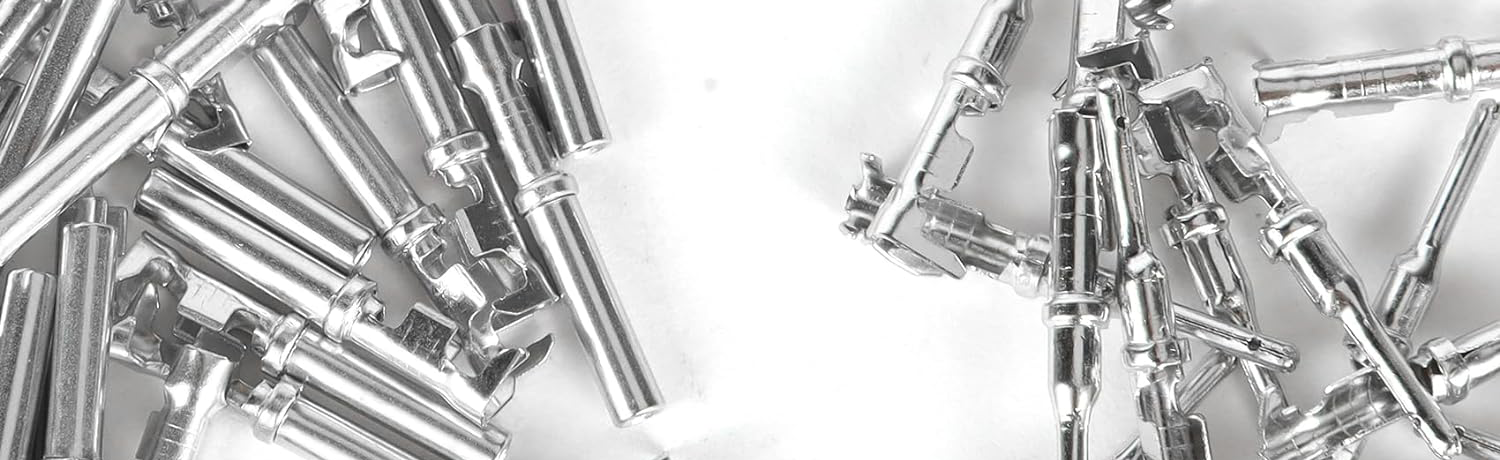
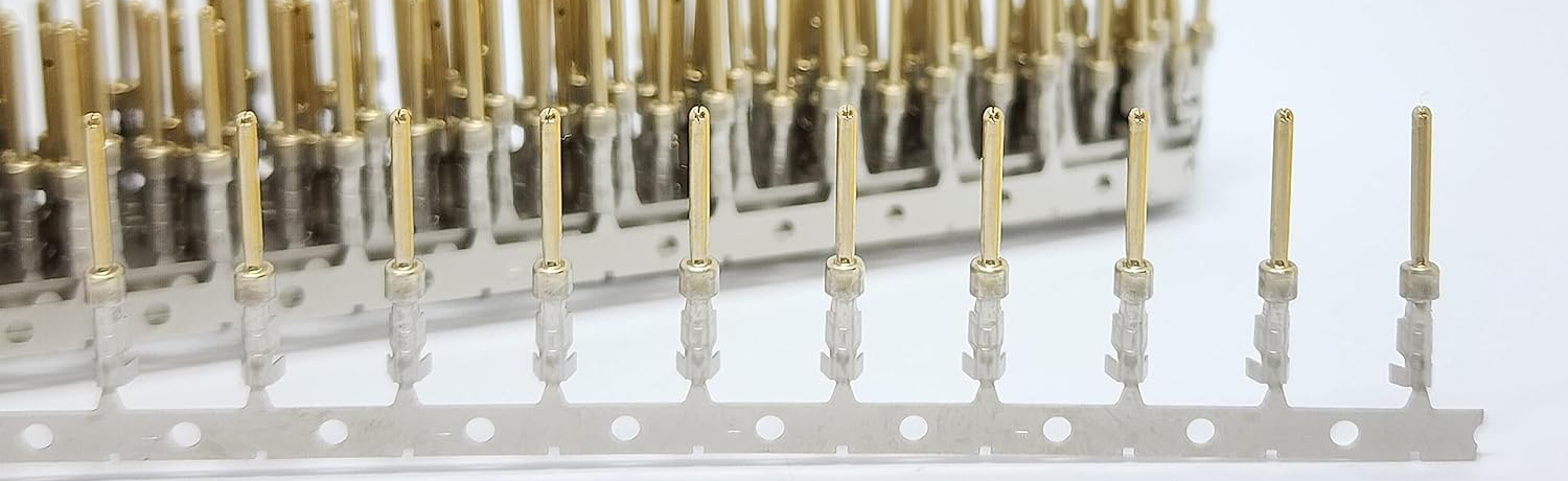
A pin contact is an electronic component that is typically used to establish a circuit connection for the transmission of electrical signals, power, or data between electronic devices. It is usually made of metal and has an elongated plug portion, one end of which is inserted into a connector receptacle and the other end of which is connected to a circuit. The primary function of the pin is to provide a reliable electrical connection that allows communication, power, or data transfer between electronic devices.
Contact pins come in a variety of types, including single-pin, multi-pin, and spring-loaded pins, to suit different applications. They usually have standardized dimensions and spacing to ensure interoperability, and are widely used in a variety of fields, including electronic communications, computers, automotive, medical equipment, etc., to connect various devices and components.
Connector pin Standards
Contact pins standards are used to ensure the interoperability and interchangeability of connector receptacles and pins so that connectors from different manufacturers can be seamlessly connected in a variety of applications.
1. MIL-STD-83513: A military standard for miniature connectors, especially for aerospace and military applications.
2. IEC 60603-2: A standard issued by the International electrotechnical Commission (IEC) that covers a variety of connector types, including D-Sub connectors, circular connectors, and more.
3. IEC 61076: This is the standard used for industrial connectors, including a variety of connector types, such as M12, M8, and so on.
4. IEEE 488 (GPIB): It is used for General Purpose Instrument Bus connectors, which are used for connection between measurement and instrumentation devices.
5. RJ45 (TIA/EIA-568): Standard for network connections, including Ethernet connectors.
6. USB (Universal Serial Bus): The USB standard defines the various USB connector types, including USB-A, USB-B, Micro USB, USB-C, and others.
7. HDMI (High-Definition Multimedia Interface): The HDMI standard applies to high-definition multimedia connections, including video and audio.
8. PCB Connector Standards: These standards define the spacing, shape, and size of pins and sockets to ensure that they can be properly aligned on a printed circuit board.
How connector pins are crimped
socket contacts are usually connected to wires, cables, or printed circuit boards by crimping. Crimping is a common connection method that ensures a stable electrical connection by applying the appropriate pressure to fasten the pins to the wire or board.
1. Prepare tools and equipment: First of all, you need to prepare some tools and equipment, including connector pins, wires or cables, and crimping tools (usually crimping pliers or crimping machines).
2. Strip insulation: If you are connecting wires or cables, you need to use the insulation stripping tool to strip the insulation to expose a certain length of the wire.
3. Select the appropriate pins: According to the type and design of the connector, select the appropriate connector pins.
4. Insert the pins: Insert the pins into the exposed part of the wire or cable. Ensure that the pins are fully inserted and in close contact with the wires.
5. Install the connector: Place the connector with the end of the pin into the crimp position of the crimping tool.
6. Apply pressure: Using the crimping tool, apply the appropriate amount of force to make a tight connection between the connector pins and the wire or cable. This usually results in the metal part of the pins being pressed together, ensuring a firm electrical connection. This ensures a solid electrical connection.
7. Checking the connection: After completing the crimp, the connection should be carefully checked to ensure that the pins are firmly connected to the wire or cable and that there is no looseness or movement. The quality of the electrical connection can also be checked using a measuring tool.
Please note that crimping requires the proper tools and skills to ensure a proper connection. If unfamiliar or inexperienced with this process, it is advisable to seek professional help to ensure a safe and reliable connection.
How to remove the contact pins
To remove crimp pins, it is usually necessary to be careful and follow the following steps.
1. Tool Preparation: Prepare some small tools, such as a small screwdriver, a thin pick, or a special pin extraction tool to help remove the pins.
2. Find the location of the pins: First, determine the location of the pins. The pins may be connected to sockets, circuit boards, or wires. Make sure you can accurately identify the location of the pins.
3. Handle with care: Use tools to carefully maneuver around the pins. Do not use excessive amounts to avoid damaging the pins or surrounding components. Some pins may have a locking mechanism that needs to be unlocked to remove them.
4. Pin Unlocking: If the pins have a locking mechanism, first try to unlock them. This usually involves gently pressing or pulling up on the locking mechanism on the pin.
5. Remove with a tool: Use a tool to carefully remove the pins from the socket, circuit board, or wires. Be sure not to damage the socket or other connector parts during this process.
6. Inspect the pins: Once the pins have been removed, inspect their condition. Make sure it is not damaged so that it can be reused if needed.
7. Record and mark: If you plan to reconnect the pins, it is recommended that you record the position and orientation of the pins to ensure proper reconnection.
Please note that removing the pins may require some patience and careful handling, especially in tight spaces or with locking mechanisms. If you are unsure how to remove the pins, or if they are very complex, it is best to ask a professional or technician for assistance to avoid damage to the connectors or other equipment.